-
Your shopping cart is empty!

CHECK OUT OUR
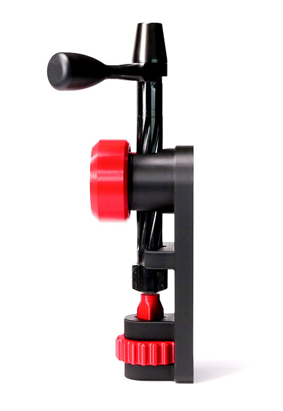
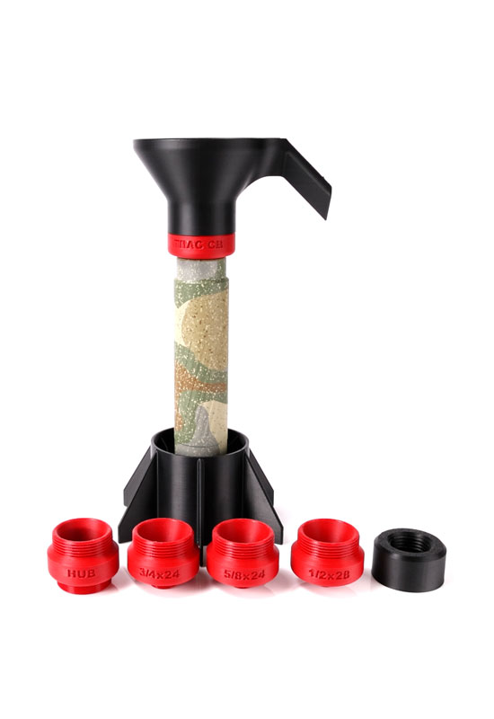
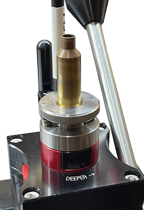
POPULAR PRODUCTS
PRIMALRIGHTS


We spend countless hours in the field using the items we sell to ensure we can provide the most reliable and accurate information possible about our products.
WE'RE MORE THAN A RETAILER!
FAITH
Despite society's continued slide into depravity, we have ultimate faith in God to guide us through this journey. We happily share the good news of our Lord Jesus Christ with everyone we encounter.
Through Him, all things are possible.
HONESTY
We say what we say and sell what we sell because we believe in it completely. Making a sale is not important. We love this sport and want to make sure your goals are realized. Your money is safe with us. Your trust is safe with us.
LOVE
We wouldn't spend countless hours testing, proofing, and using the equipment we sell if we didn't truly love it. We wouldn't spend the endless hours on the phone with our customers if we didn't appreciate you and truly want to help.
"Giving customers the best possible information to use when making purchasing decisions is the most important part of our job. If we don't know our products, we can not help guide our customers to the equipment that will best fit their specific application."
- Greg Dykstra
"EXPERIENCE is the fire in which THEORY burns and TRUTH emerges."
- Greg Dykstra
President
Primal Rights, Inc
START YOUR JOURNEY TO BECOME A
STUDENT OF THE DISCIPLINE
Primal Rights offers training on how to advance your skill set as a precision rifleman. Greg instructs on all areas necessary to succeed within this discipline. Learn how to properly drive a rifle, handload, choose equipment, walk with Christ, and much more. Read articles, watch videos, have phone conversations with Greg, or make the journey to come here to train with him 1-on-1.
- NEVER STOP LEARNING -

YOU CAN'T
PAY SOMEONE TO CARE
They either care, or they don't. Anyone that has ever spoken with Greg Dykstra, will tell you he cares deeply about this discipline and each customer, student, and vendor we work with.
We do NOT SHIP Outside the USA
If you live outside the USA, please order from our international distributor - Graf & Sons


Visit the Primal Rights
YouTube Channel
There you'll find hundreds of videos teaching about how to achieve the highest goals you can envision in the precision rifle discipline.
Any questions? Feel free to
Contact Us
.png)
18570 Chance Rd
Meadow SD 57644

605-554-1911

sales @ primalrights.com